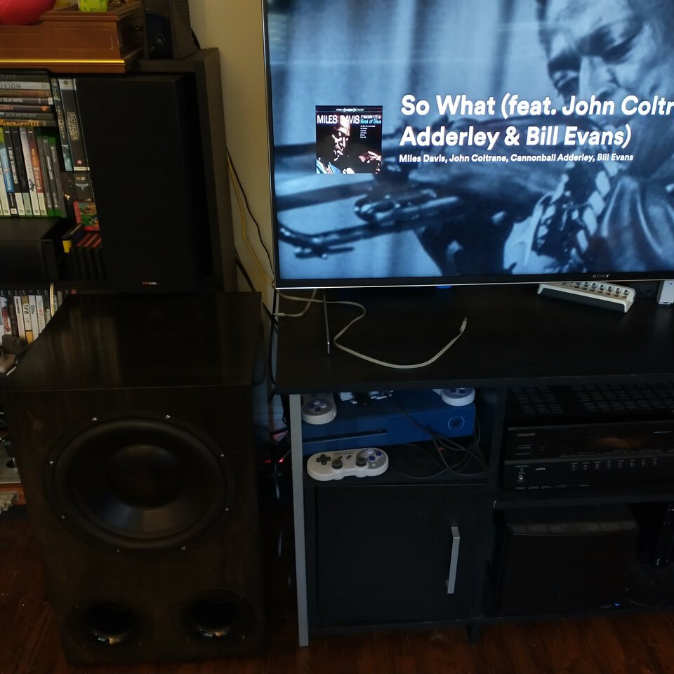
Back in the day I set up a home theater system, with a subwoofer. It broke during a move, and then I fixed it, and then it broke again, and it sat there doing nothing for three and a half years and then the next time I moved it went in the garbage.
Flash forward a couple years, I'm in front of my teevee during a pandemic, there's no sound output below 100Hz or so. A Twitter mutual talked about him buying a subwoofer and I thought to myself that I should get around to replacing the broken one, and then, "I should just make a subwoofer instead of buying one. It's just a box with a speaker driver and an amplifier, right? How hard can it be?"
So first thing's first, I'm in a much smaller house than I used to live in, space is at a premium. I have a space next to the TV stand, 25 inches high, about 15 inches deep. I'm not sure how wide I can go but a subwoofer wider than it is deep will probably look kinda weird, so let's constrain the box to this 25" by 15" by 15" volume. And, I want something that will maximize the output from this. I want to be able to tell myself that this was unambiguously better than going the boring route of just buying an expensive subwoofer from some website.
Now, how does this actually work? This is the part where I google a whole bunch of random shit about speaker design and look at various internet hobbyist communities doing projects, and I find out that everyone on internet forums are busy building subwoofers the size of the speaker from Back To The Future. Seriously, I end up looking at one called "the full Marty" that is larger than my refrigerator.
Anyway, I also don't want to build from a flat-pack kit or even from somebody else's project plans, I want to know how it works, or at least move far enough up the learning curve to satisfy my need to build something from scratch. (Various guides on the intertubes explicitly tell me not to do this but that's never stopped me before.)
But I get the general gist of it: a speaker driver is pushing air back and forth, so it needs to be in an enclosure, and that enclosure needs to be tuned to produce output in the desired range. You can just build a sealed box, which will struggle to produce output at lower frequencies, or you can add a "bass reflex port", an opening to the inside of the speaker; the speaker will produce better output at the resonant frequency of the port, which will depend on the port's length and area. The tuning frequency also depends on the internal volume of the cabinet, and the port doesn't count towards it, so I'll need to be careful building this thing so my numbers don't get screwed up!
There's a set of engineering numbers that each speaker driver has called the Theile-Small parameters, presumably named after two Speaker Scientists or something, and a bunch of equations that I will read appreciatively and not actually solve myself. Where's the simulation software; this has to already be a solved problem?
The software that everyone recommends to model speaker output is called WinISD and runs best on absolutely ancient versions of Windows, so I spin up a Windows XP virtual machine and get cracking. If the outside dimensions of the box are 25" by 15" by 15", then the largest driver I can feasibly fit in there is a 12" subwoofer driver; I find a few reasonably priced candidates and punch in the numbers. I start with the cheapest one.
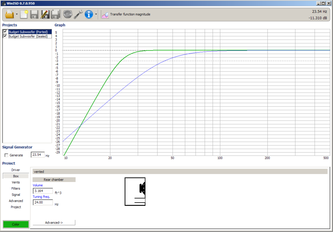
I'm just looking at the default settings that it recommends me when I plug in the driver and tell it to give me a ported or a sealed box. For the ported box it's telling me I need over 3 cubic feet and an 18" long port. The recommended sealed box is a lot smaller but it's down to -3db at 44.8Hz, that won't do at all.
But the software lets you play around with different settings and filters and so on. One of the amplifiers I'm looking at does a 6db boost at 30hz, let's model that on the sealed box, and maybe increase the size? I've got some extra room on what they recommend for a sealed box. This doesn't look too bad.
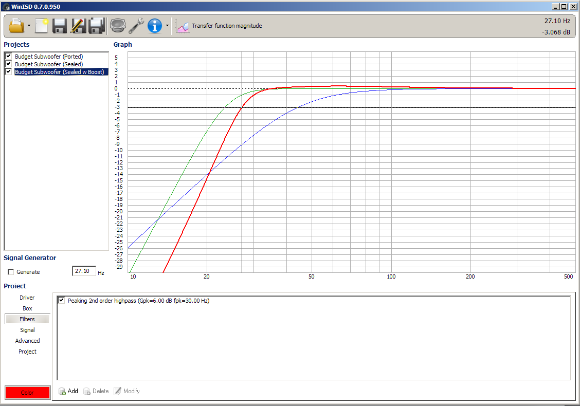
Then I go tell the model to show me what happens when I send 300 watts of power into that cheap subwoofer driver and I realize why it's cheap. One of the T-S parameters is "Xmax" - the maximum distance the driver can extend without damage. This one is pretty small - if I try to push lots of power into it, bad things will probably happen.
Meanwhile I'm agonizing over what amplifier to use. You can get amplifiers that mount into the cabinet, or that are a separate box to stick with the rest of your home theater electronics boxes. I have no clear idea of how much power I need and many of these parts are expensive without a clear reason to be expensive. The marketing around home audio stuff just feels like a very high-bullshit environment. After going back and forth between a few different models, I notice that I can probably build a decent Class D amplifier out of component parts from Aliexpress or whatever, and I research that for too long of a time. I can feel the project slipping into the "never gonna finish it" bin, so I stop all of this nonsense and find a decent price on a used amplifier on eBay. It's a Behringer NX1000D, it has a programmable digital signal processor that I can program filters into if I need to do that for some reason, and it claims to be able to shove out a thousand watts, which is definitely enough for whatever I'm building here. It isn't designed for home theater, it's marketed to professional audio users, so it has permanently attached rack mount hardware (cool!) and a super noisy fan (but that should be easy enough to fix).
Meanwhile, I'm playing around with this software and I discover there's a three-sided trade space between low frequency output, smaller box size, and power amplifier requirement, then I discover that everyone already knew this and it's a "Law" named after some guy.1
Well, the whole point of this project is low frequency output, and I'm constrained on cabinet size, and I have a very powerful amplifier coming in, so I'm pretty well set here, time to play to my strengths. I find a Dayton Audio RSS315 "High Output" speaker driver that has high power requirements and does very well in a small cabinet.
I discover that you can get decent power at lower frequencies by making the box larger than "optimum" and then tuning the port to a lower frequency. This output graph is looking good! But the port size seems too long, how can I stick a 42" vent into a box that can't exceed 24" high. Elbow joints?
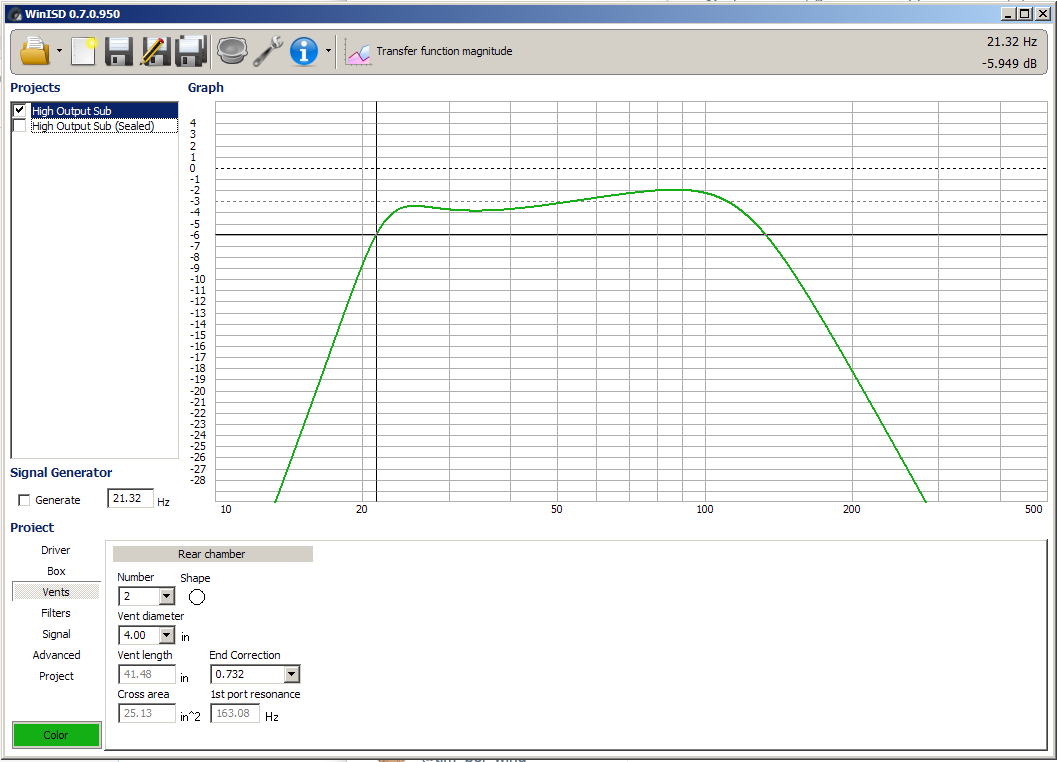
The port opening needs to be wide enough so the air doesn't move through it too fast, because then it becomes turbulent (and audible). But a wider port needs to be longer (for the same tuning frequency). There are several independent variables to play with and get balanced.
Eventually I settle on a box with 2.2 cubic feet of internal volume and a port tuned to 22Hz. I think I can build this. I can either use two 3" ports or build a rectangular port right into the box. It should have a nice flat frequency response, at high power it will be very loud without damaging the driver, and at normal volumes the air flow through the box should be slow enough that I won't hear it over everything else.
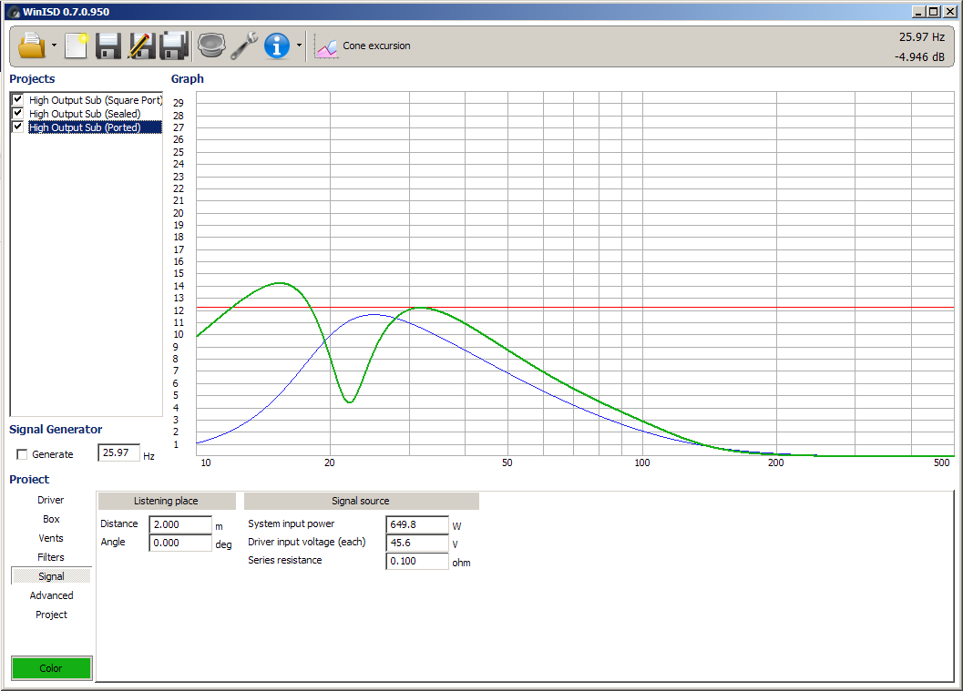
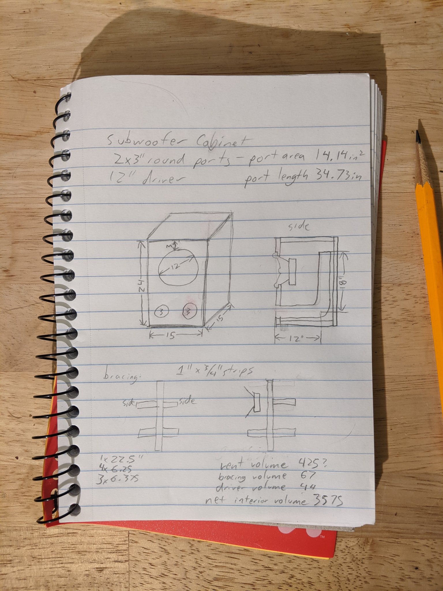
I went and modeled the box for the subwoofer project in my favorite CAD suite, pictured below. I don't have quite as much internal volume or port length as I simulated - I'm down to 2.07 cubic feet, and a port tuned to 24.3 Hz. But, I'm pretty close, it will probably fine. The simulator says I lose a little sound around 20-23 Hz, but not that much, and I can't really hear that low anyway.
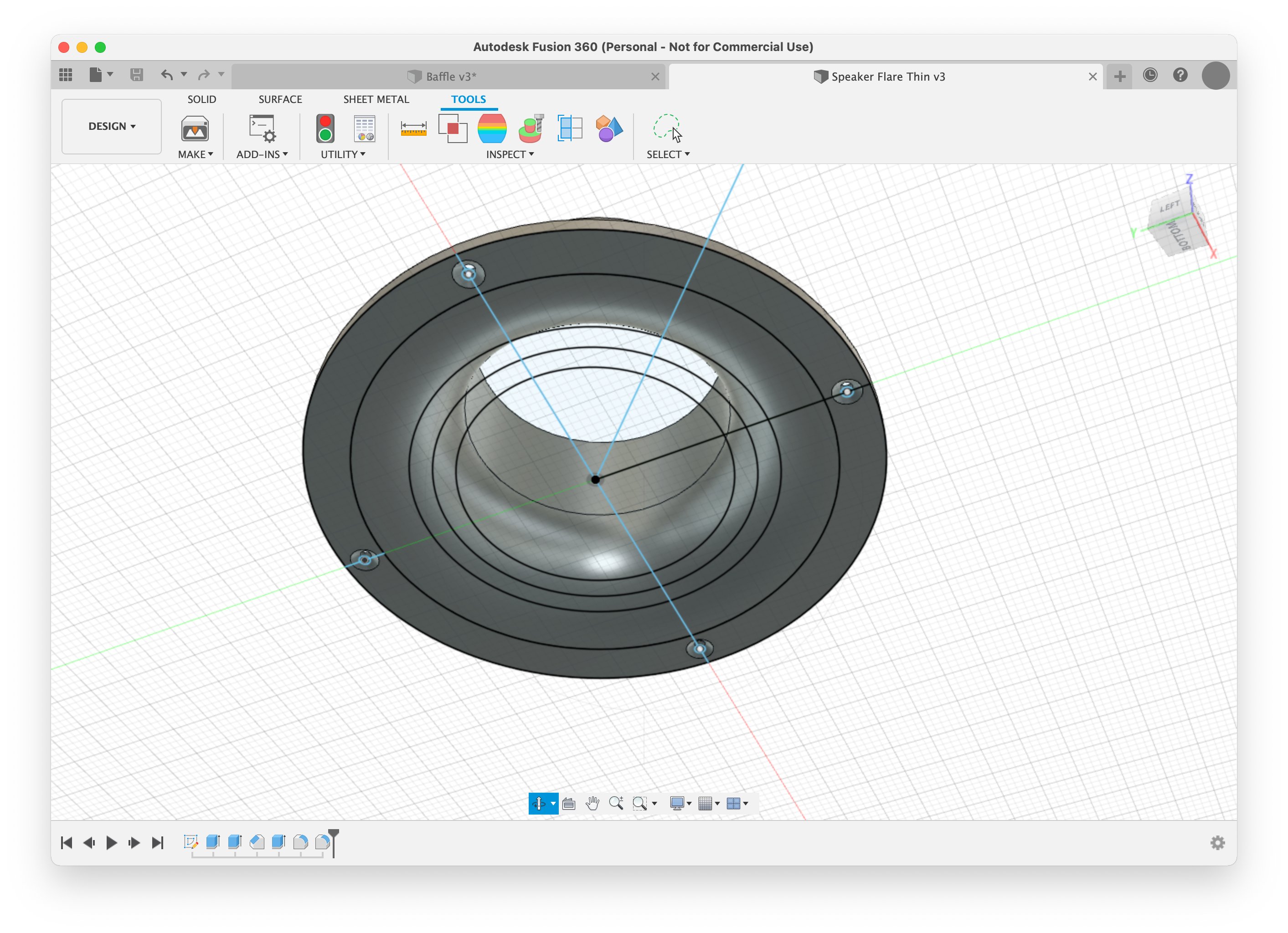
I've heard that the ends of the ports should be flared, so that the air flows better through them. This makes sense, and it would look nicer too. They sell flared port ends on Amazon but they're like $25 each, and I'm never paying that much for a piece of plastic ever again. So, I throw together a speaker port design for my 3D printer.2 If I print these out of ABS plastic, I can use standard ABS sewer pipe from the home improvement store for the rest of the port length and it will glue together very easily.
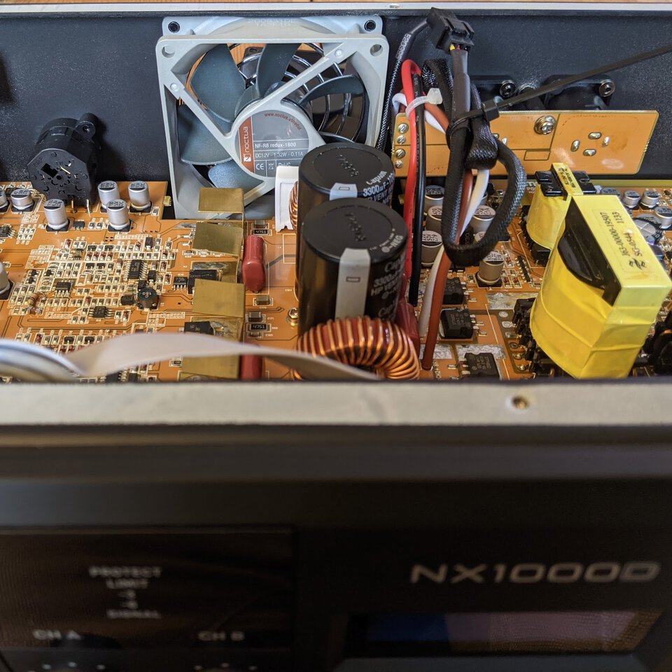
Oh, right, the amplifier. The fan is hilariously noisy; this was not designed to sit in the same room as the speaker. I replace it with an overpriced gamer fan, it's dead silent now. Sure, it's pushing less air, but it's probably fine.
The amplifier is designed for professional audio, where they use different connectors for everything. LFE output from the TV receiver (an RCA jack) goes to one of the XLR ports on the back. Output from the amplifier to the speaker is a Neutrik connector. These are fucking neat, they rotate and go "click" and stay secured. I'll use one on the speaker cabinet, too, instead of those crappy wire terminals for banana plugs that you see on speakers everywhere. It's just a couple bucks for the connector, and I can make a cable easily.
At some point in here I decided I don't want to build the speaker cabinet out of fiberboard. You have your basic hierarchy of materials, right? Particleboard, like your IKEA furniture, is at the very bottom, medium density fiberboard (MDF) is exactly one (1) step higher, above that you have crappy plywood, then good plywood, then solid hardwoods. Most speakers you buy are made out of MDF. It's a bunch of wood pulp held together with glue and formaldehyde. It's dense, which is good for a speaker, and it's very consistent when you're trying to machine it, which is good for mass production. I've used it before. It sucks and I don't want to use it.
The internet suggests that the next step up is "Baltic Birch" plywood. It's plywood, but it's high quality plywood, lots of plies of a nice-looking hardwood. It's light in color but I hear it takes stain reasonably well. I find a local wood shop that has some and ask them for a quote on cutting it. They have a CNC router, even, so I converted my pencil-and-paper format drawing into something they can use:
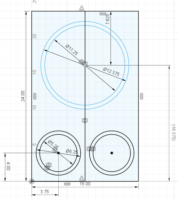
and then they told me that there's a three week wait on that router. I guess things are busy! So I just have them cut the panels instead. (Paying for this was annoying but I lost my table saw when I moved so I gotta do what I gotta do).
I'll router out circles with my old shitty Harbor Freight router and a circle cutting jig from the internet.
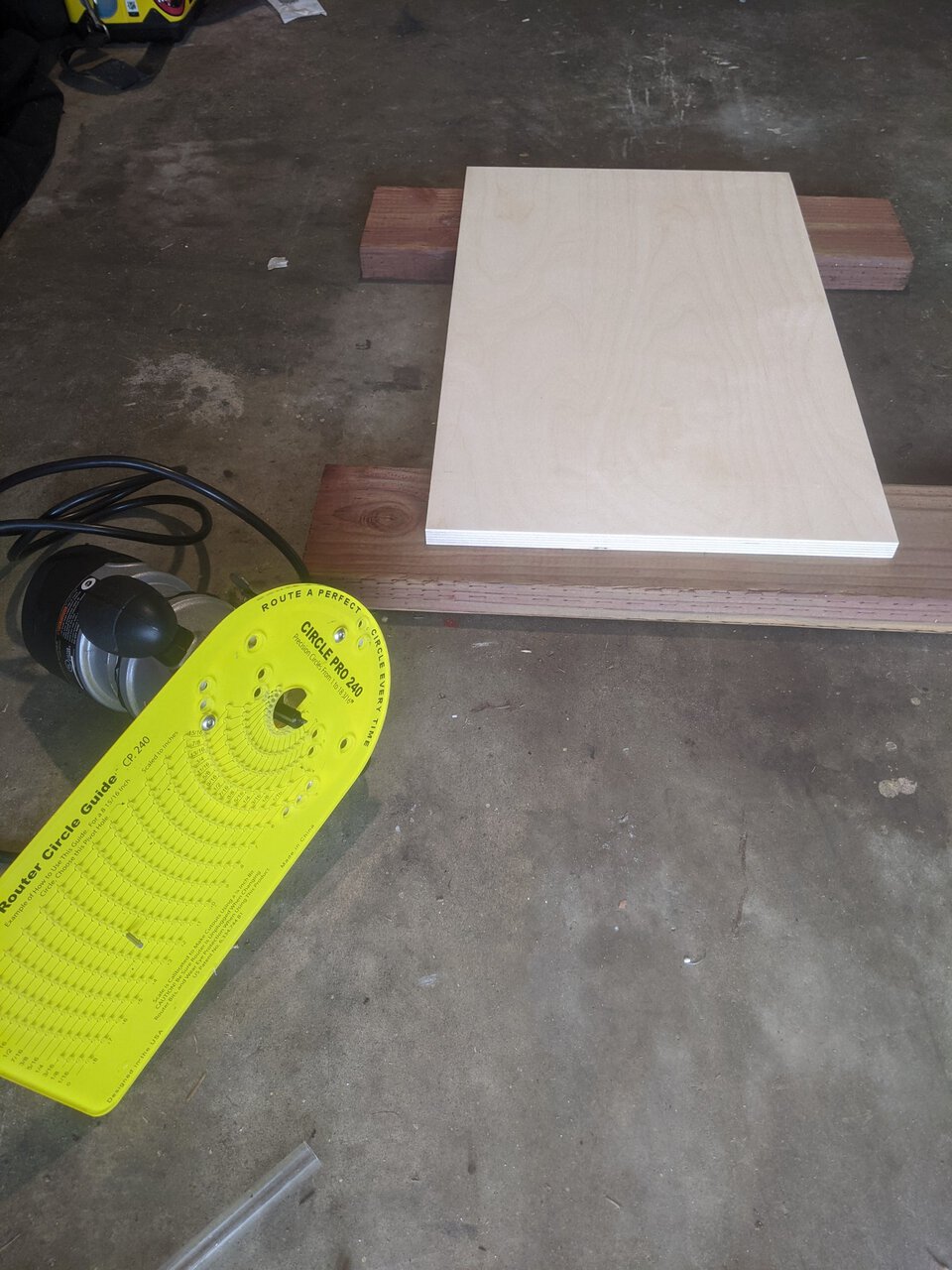
You drill a small guide hole, a pin goes in there and into the circle jig, and then you mill out a nice, clean circle.
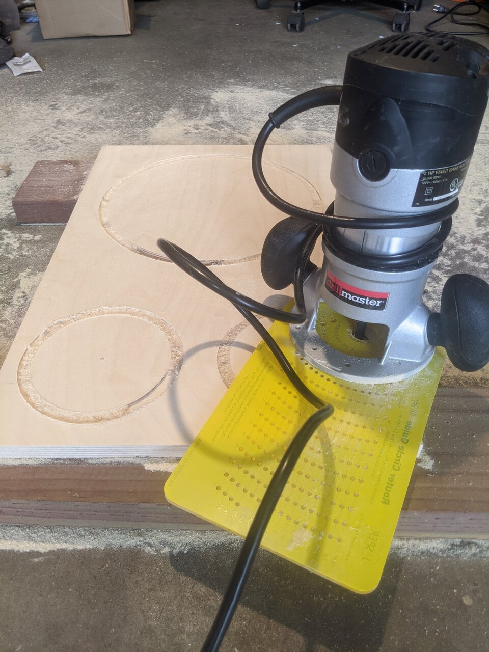
So far so good!
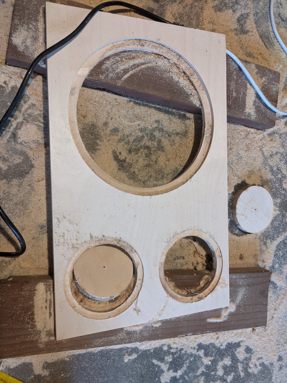
Not bad at all! Circles came out nice and clean. (Note to self: don't fuck with the router depth between passes or it will never line up right again)
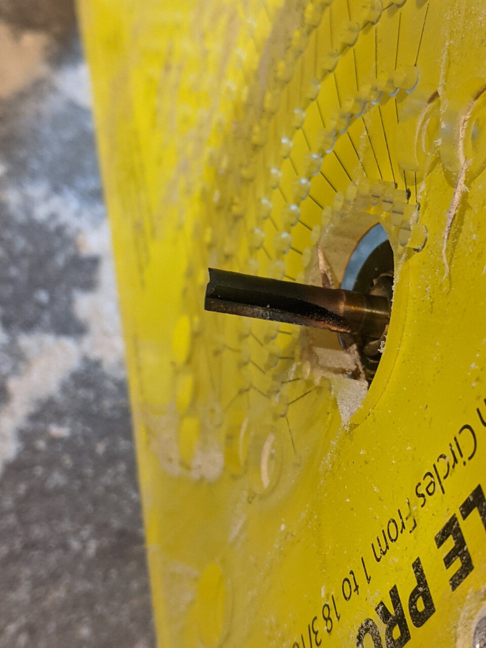
This router bit, on the other hand, is burnt to fuck. I thought I was going slow, so I'll just blame Harbor Freight on this one.
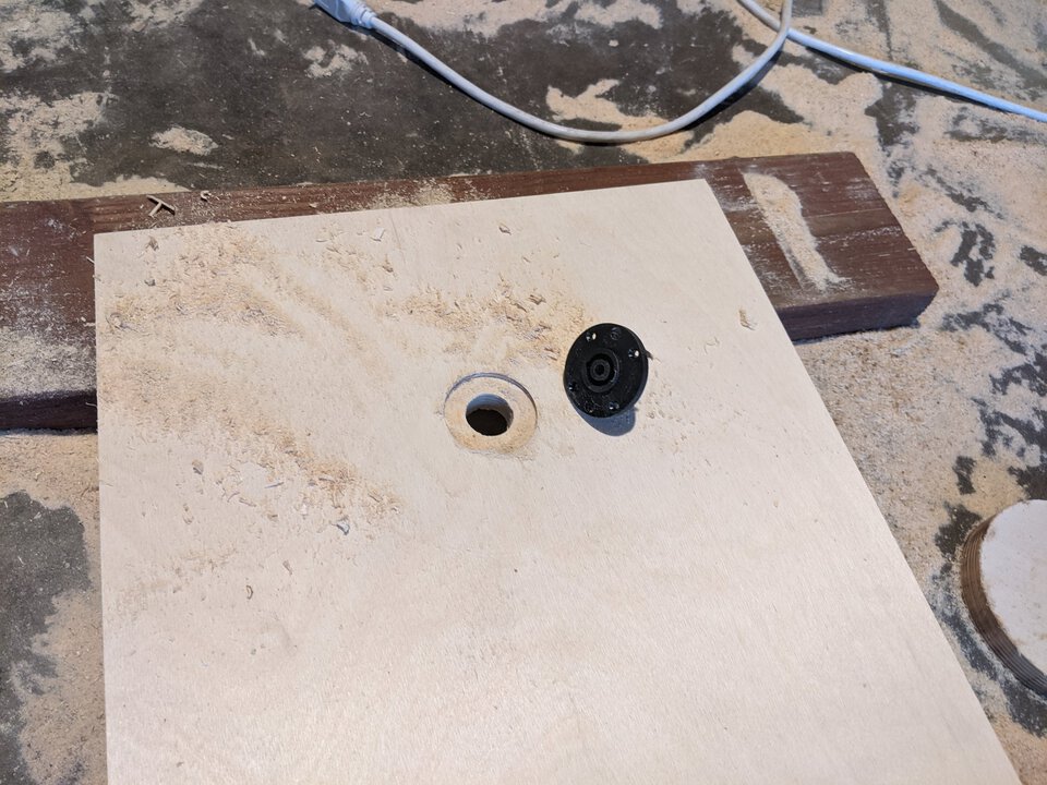
I got one last cut out of that bit, for the Neutrik wire connector I'm putting on the back panel. Now it can go in the discard pile. Everything in my garage is now covered in dead tree fragments.
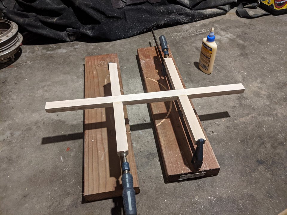
I have some strips of plywood that I'm gonna glue together to brace the inside of the cabinet. Gluing these together first, want to do this one step at a time.
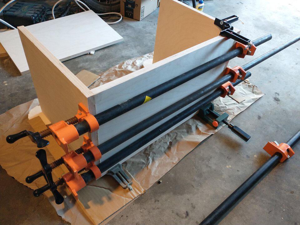
I want to glue the side panels all at once but I can't seem to get them square. If I had way more of those corner clamps I could do it. Instead, glue one side, wait for it to dry, then glue the other.
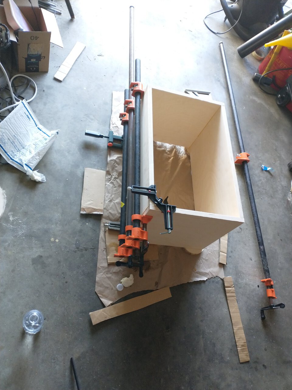
It works, but it would have been smarter to glue it the other way around so that I'd be gluing an outer panel each time instead of trying to cram in an inner panel. It's probably fine, just have extra glue all over the inside.
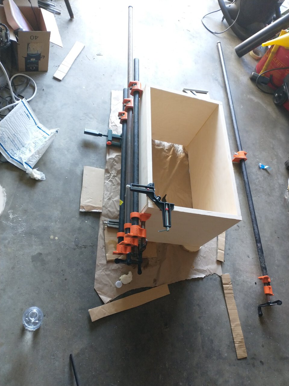
Also finishing the braces. This was a pain in the ass to clamp this way.
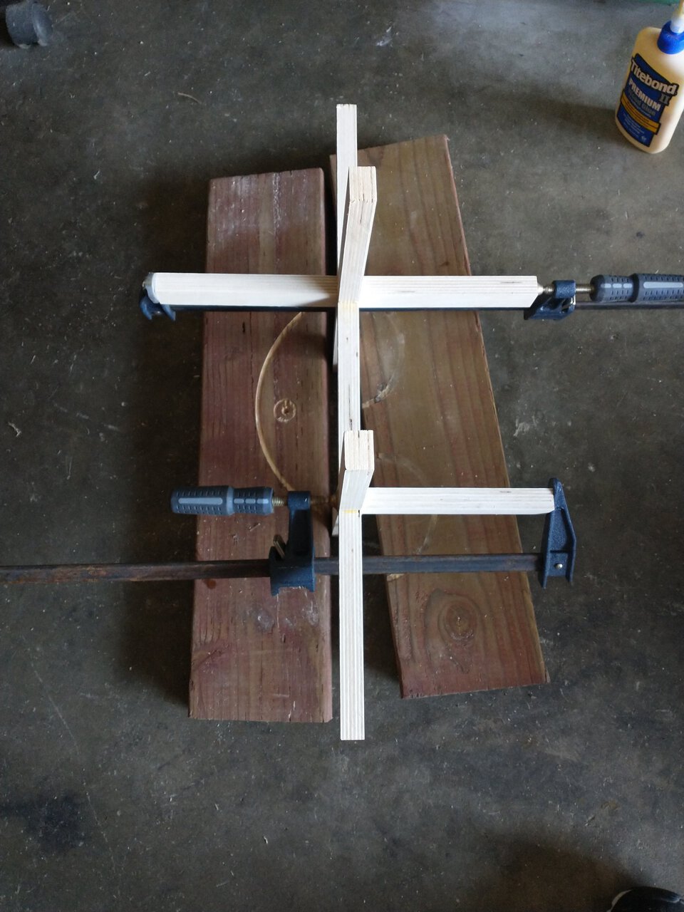
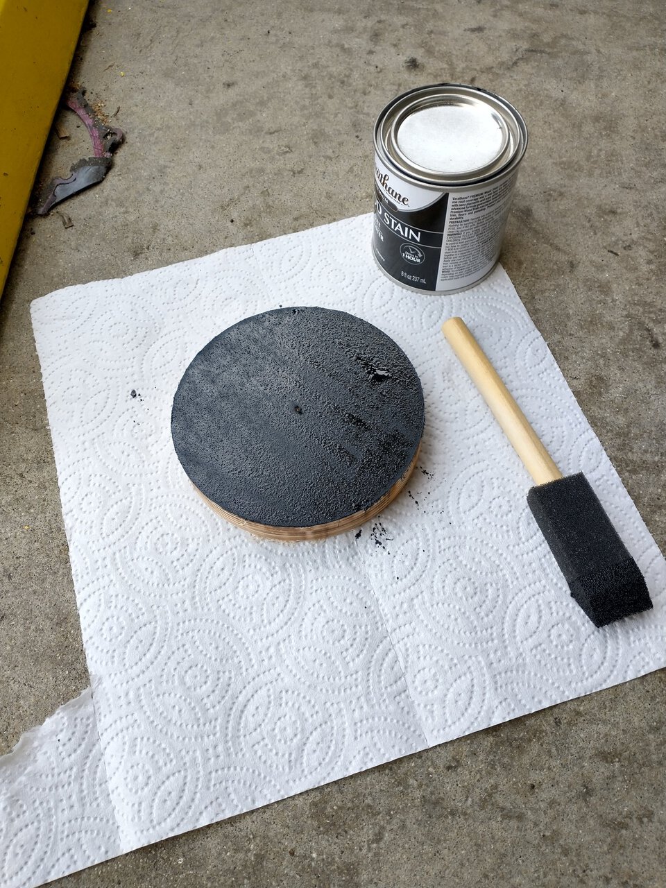
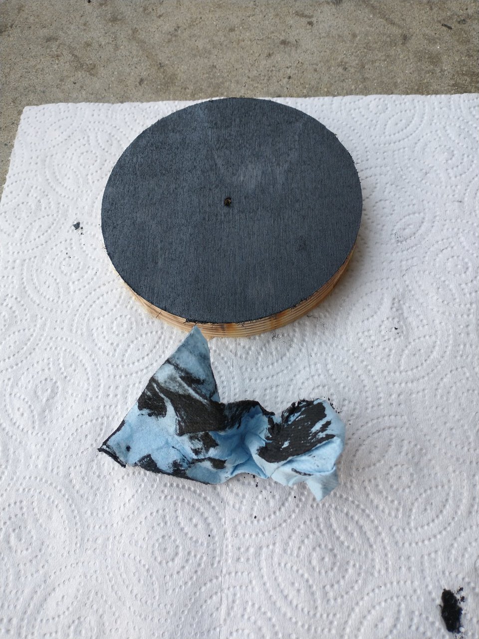
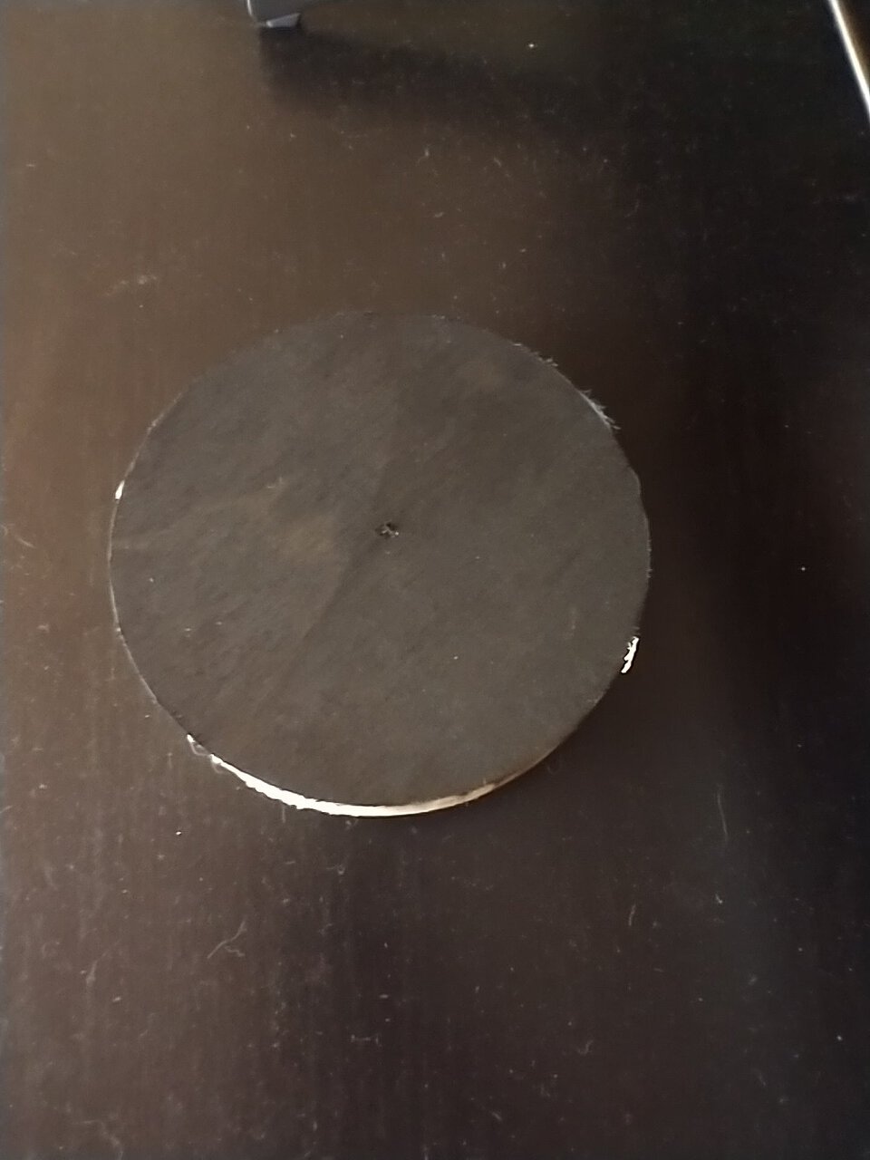
It's a good time to test out the wood stain on one of the scrap pieces. Brush on, wait a few minutes, wipe off. Looking for a similar black color as the TV stand, but a stain instead of paint so there's still some wood grain there. I like it.
Clamping the front and back on there at the same time, with the bracing inside. Got enough clamps! Nice even pressure all around.
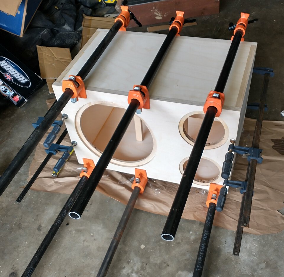
Surface prep is extremely important but it's so fucking tedious. I carefully chisel away all the glue runs, sand smooth with increasingly fine paper. I'll start with the power sander at 100 grit and then go by hand through 120 and 150 and 180 and a little while at 220. Use the sanding block to just slightly break the corners as well, this helps the finish stick well.
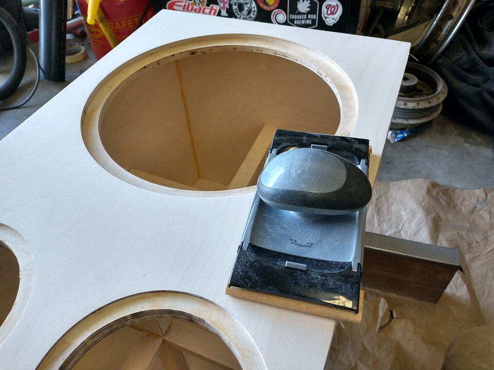
I'm gonna stain the bottom panel first, just in case. It's very important to wipe off excess stain, or it won't dry right. I like it so far.
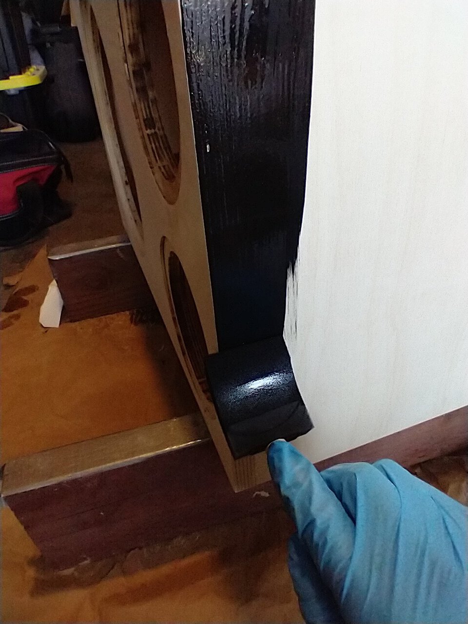
I expected the front panel to come out darker but I'm still okay with this. One side I needed to redo -- I didn't wipe fast enough, so it's not drying right. The fix is to wipe it down with paint thinner, then apply a new coat of stain. Gotta get this right before the finish layer, once that clear coat goes on there's no fixing anything underneath it.
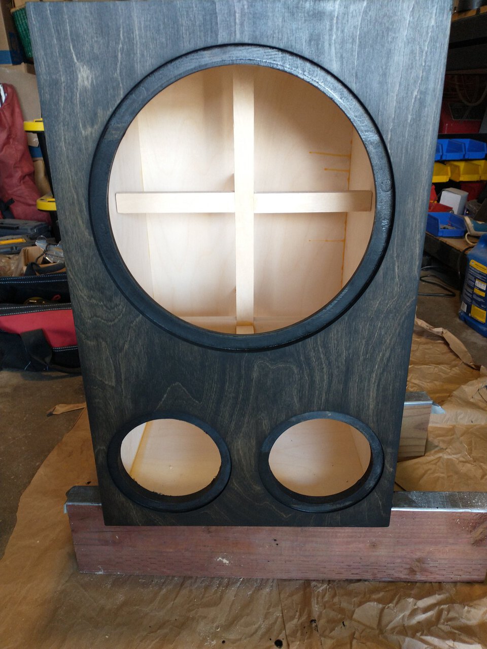
The stain is done and I get working on the finish: oil-based gloss polyurethane. Again I start with the bottom of the box. I brush on three coats - and I don't like how this came out. It's nice and shiny, but the thickness is very uneven. I'm not going to redo it because it's the bottom side of the box, but I don't want the rest to come out like this.
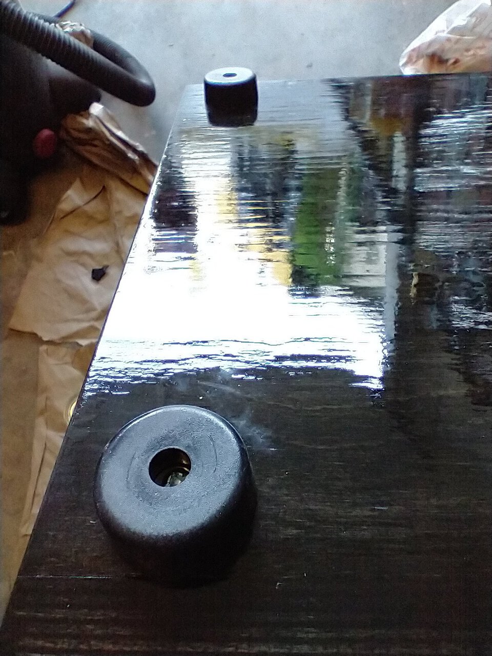
In the past, I've gotten excellent results from a lot of coats of super-thin wipe on poly finish. But it's so time consuming! To get a thick enough finish, you need about ten coats. Well, if it's going to take a long time to finish, no time like the present to get started.
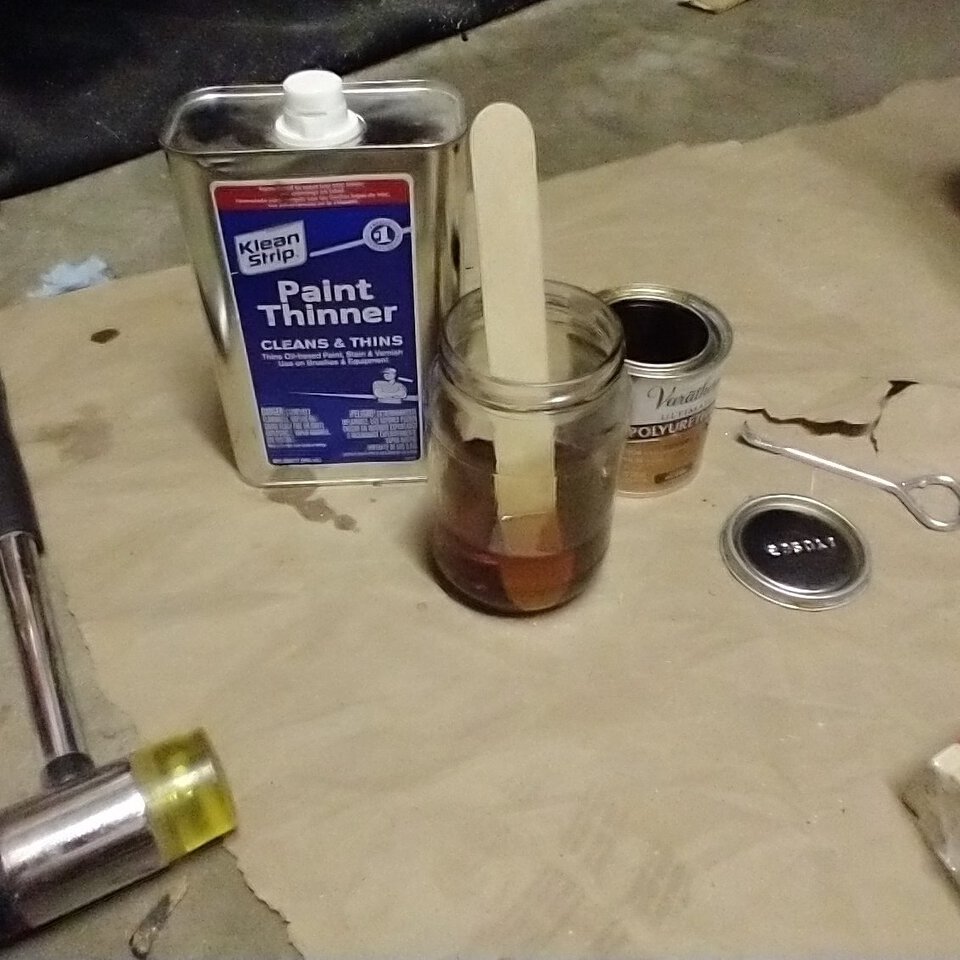
So here's how this works:
The first coat, it will feel like you're rubbing off the whole coat you just put on. Two steps forward, one step back, the whole way.
While I'm waiting for the seventh coat to dry, let's start getting the bass reflex ports built. I planned on two of them, 3" each, flared at the end. I printed the flare so that it's the same thickness as cheap ABS sewer pipe from the hardware store. The slanted cut at the end will help it fit in the box. Might help with airflow too, I don't know.
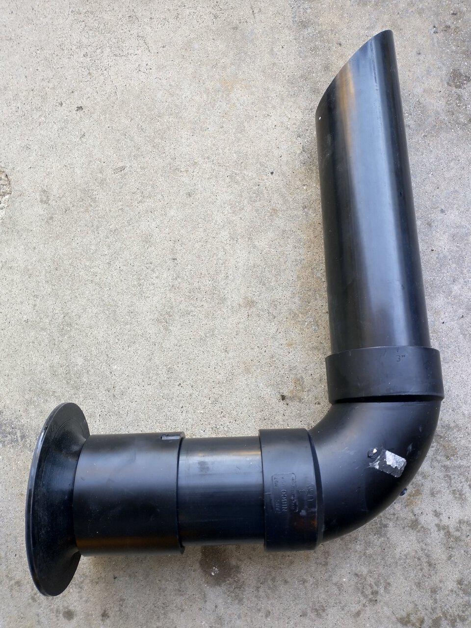
Gluing together the lower segments with ABS plumbing cement. This is just ABS plastic dissolved in acetone, you can make it yourself if you can't find any. Acetone dissolves ABS very quickly. When the cement dries, it's one contiguous piece of plastic.
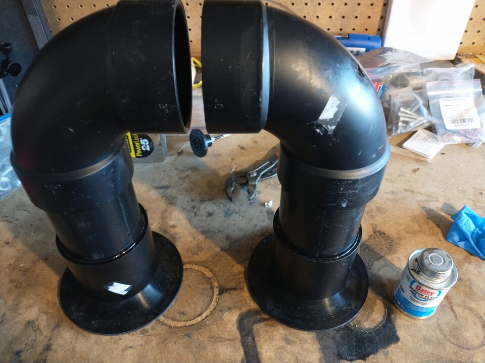
It's important that the ports are the same length, so they match frequencies.
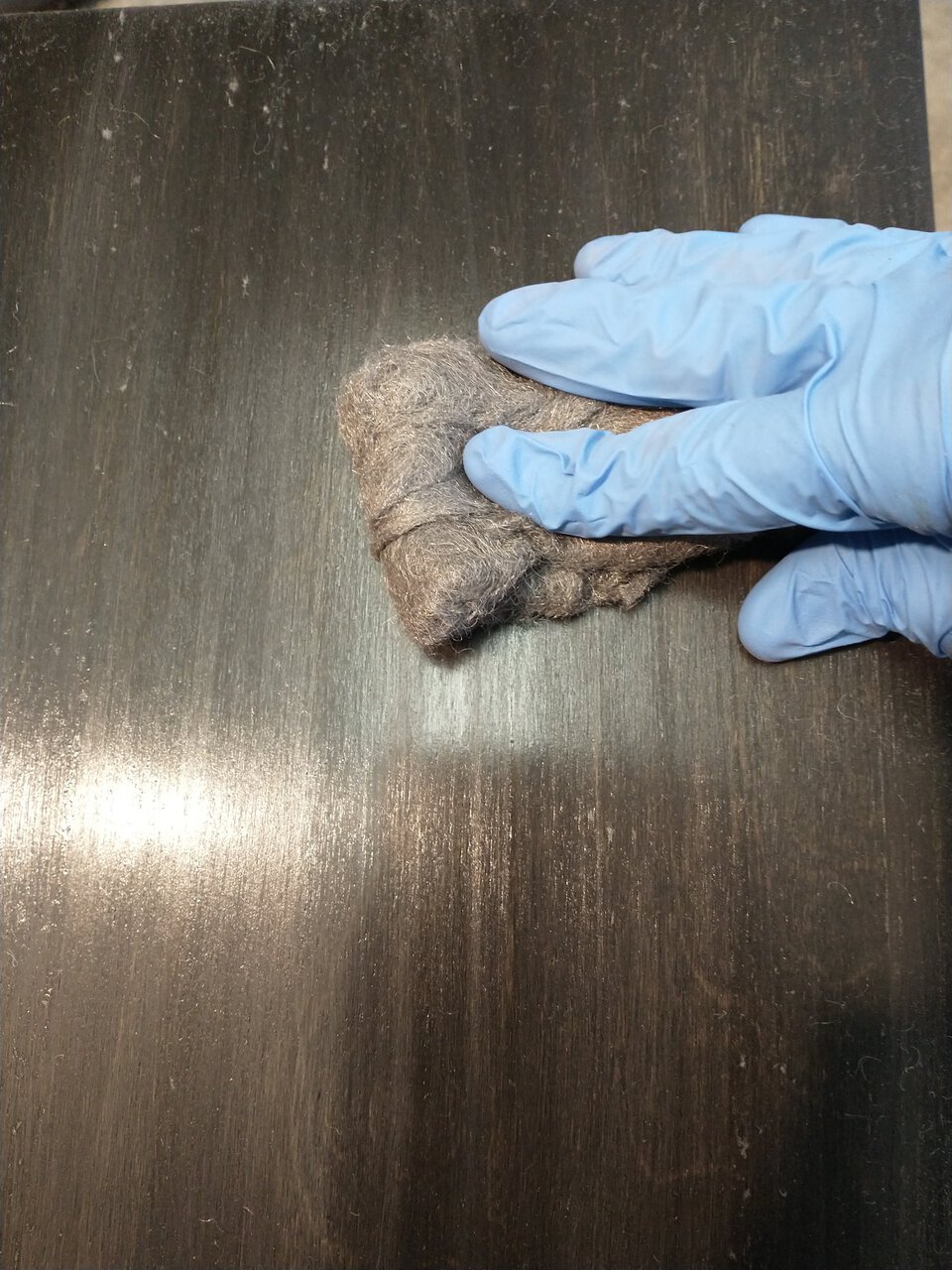
After ten coats of wipe-on poly, I'm done with the finish. (I switched to 0000-grade steel wool for the last couple coats). There's a run on the side that will face the wall, I don't have the patience left to sand it out and do another three coats. The show side is fine. I'm almost there!
Gluing together the last segment of the bass reflex ports. This is a point of no return: after the glue dries they won't come out without cutting them or cutting the box
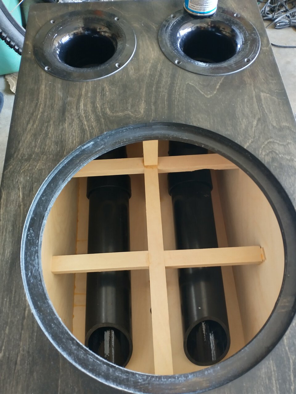
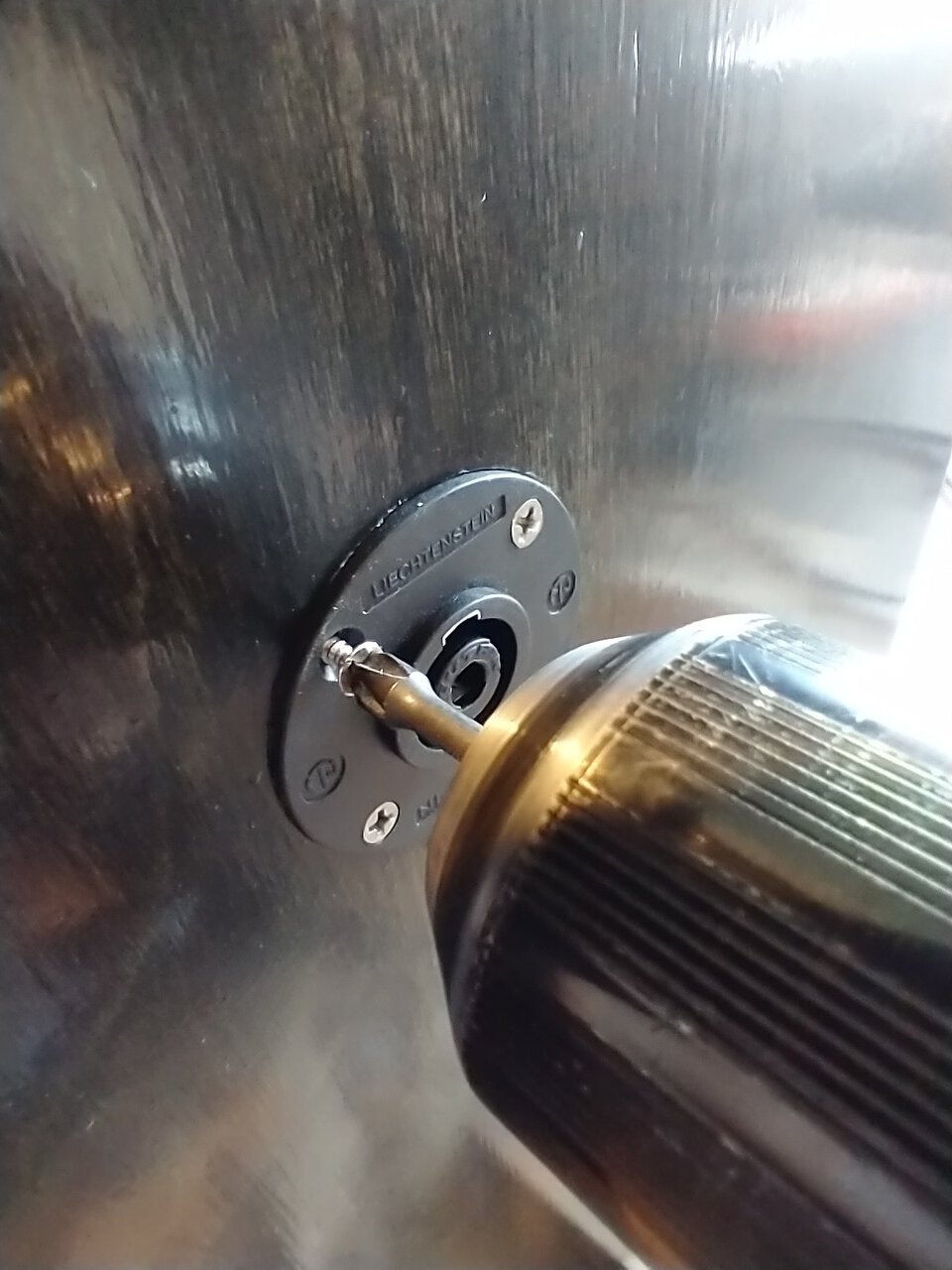
Now it's just a matter of putting together the pieces. I'll use wood screws to hold in the ports and the wire connector on the back. For the driver, I'll use tee nuts, because it's very heavy and I don't trust wood screws to do the job.
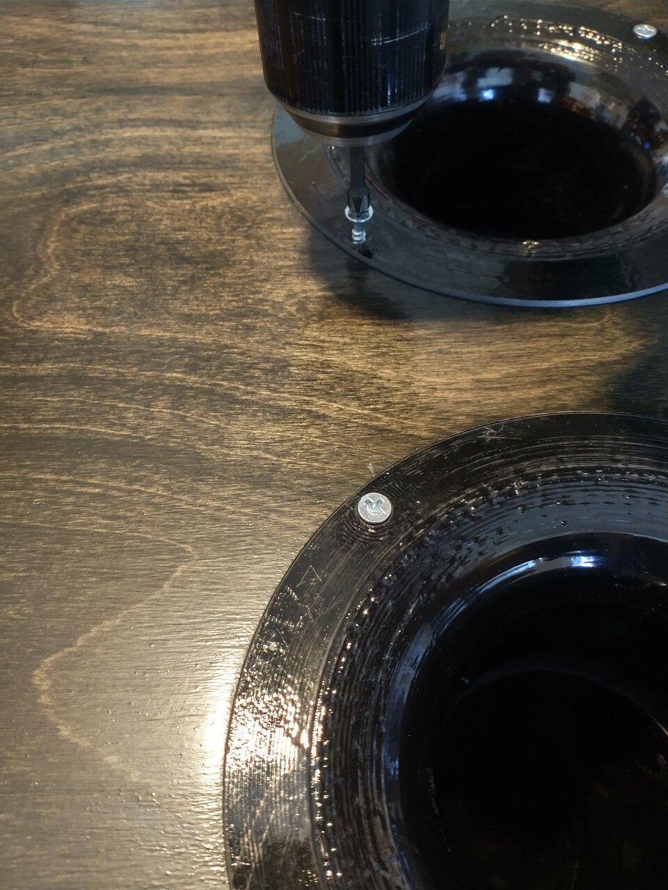
Here I encounter a setback. I bumped the cabinet off of the boards it was sitting on, and it fell a couple inches. The 3D-printed port flares cracked. They're not strong on that axis, I suppose. Time to test my plastic welding skills.
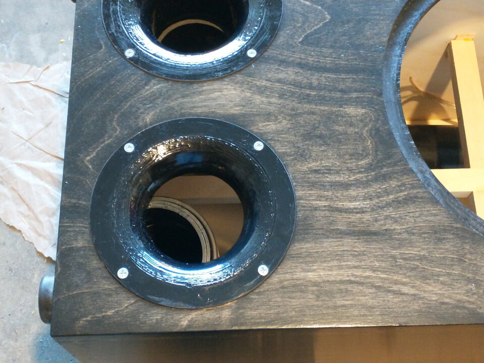
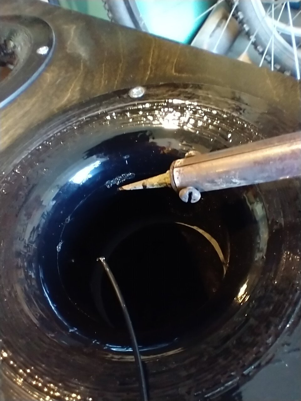
You take a soldering iron and melt the plastic together, using a piece of ABS filament as a filler. It's kind of like TIG welding. (Also like TIG welding, I'm not very good at making it come out right.) Then you cut away any excess, and fill in the gap with ABS cement. I used to fix up busted motorcycle fairings with this method.
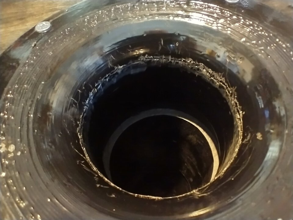

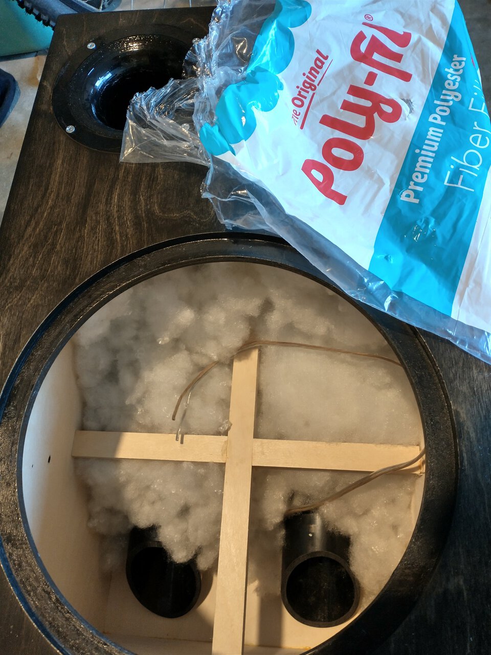
Where was I? Last thing before installing the driver: pack it full of polyfill like a teddy bear. This should smooth out the response and drop the resonant frequency of the box slightly. The ports aren't quite as long as I'd planned for, but if this drops the frequency by 1 Hz or so I'll be in good shape. (It's funny how if you buy this at a store it's $3.40 but if you buy online it's "$15, free shipping!")
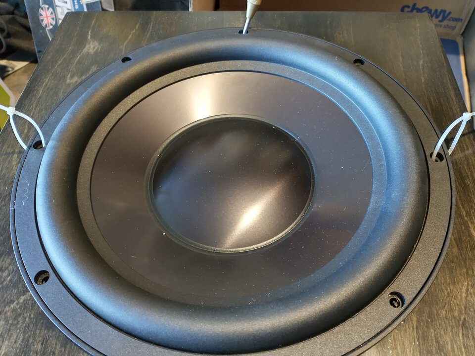
I'll lower the driver in with zip ties and mark where to drill holes for the tee nuts. If I screw this up, I can rotate the driver 22.5° and try again.
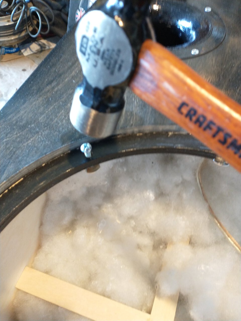
If I was smart, I would have put in the tee nuts before gluing together the box, so I could tap them in with a hammer. Well...
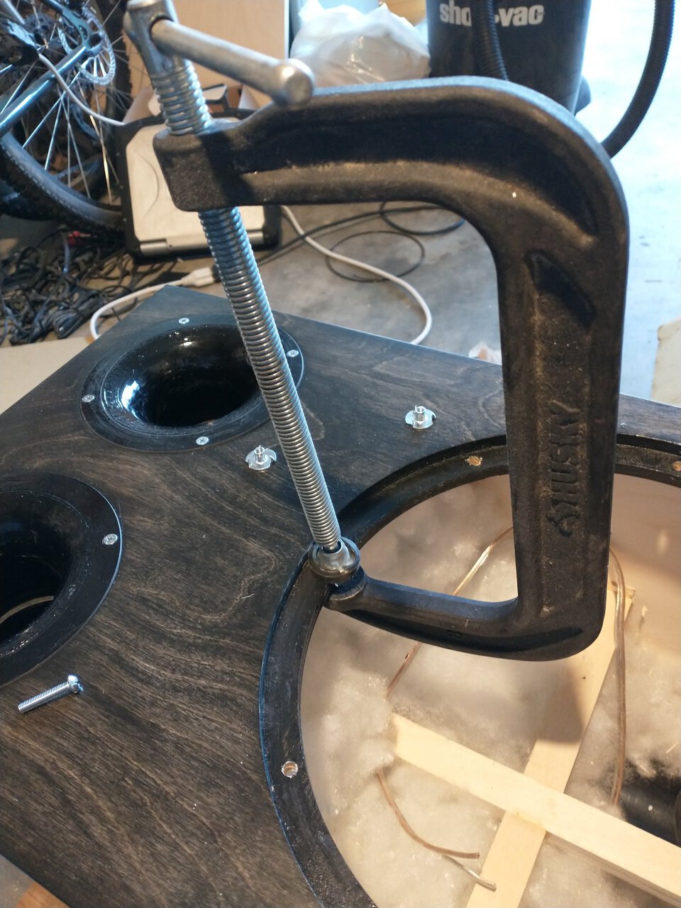
I lower the driver into the hole, it's very snug. At this point it becomes clear that I didn't line up the screw holes right. I have two problems:
So, let's fix this. I grab a big bolt and come in from behind. (I can feel where the bolt is touching the back of the speaker driver because it gets grabbed by the speaker magnet.)
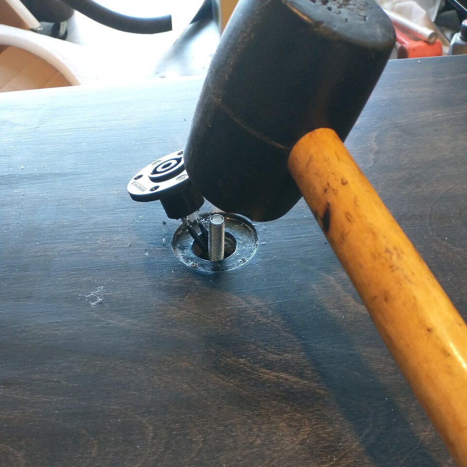
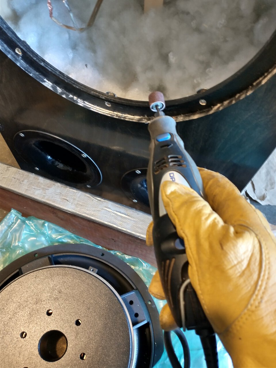
Take the Dremel and give myself another millimeter of breathing room. I tap the tee nuts back out with a hammer. The driver drops back in easily, rotated π/4 radians from where it was before. This time I'll use a wood screw to hold it in place while I drill the other holes.
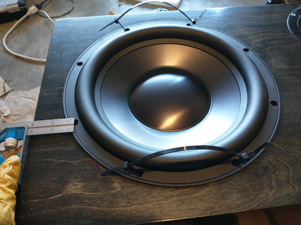
and don't forget to connect the wires before dropping in the speaker driver!
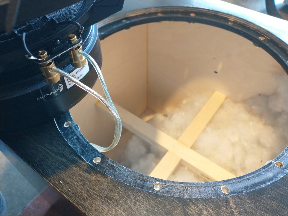
It's in!
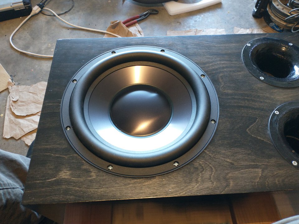
This thing looks fucking magnificent.
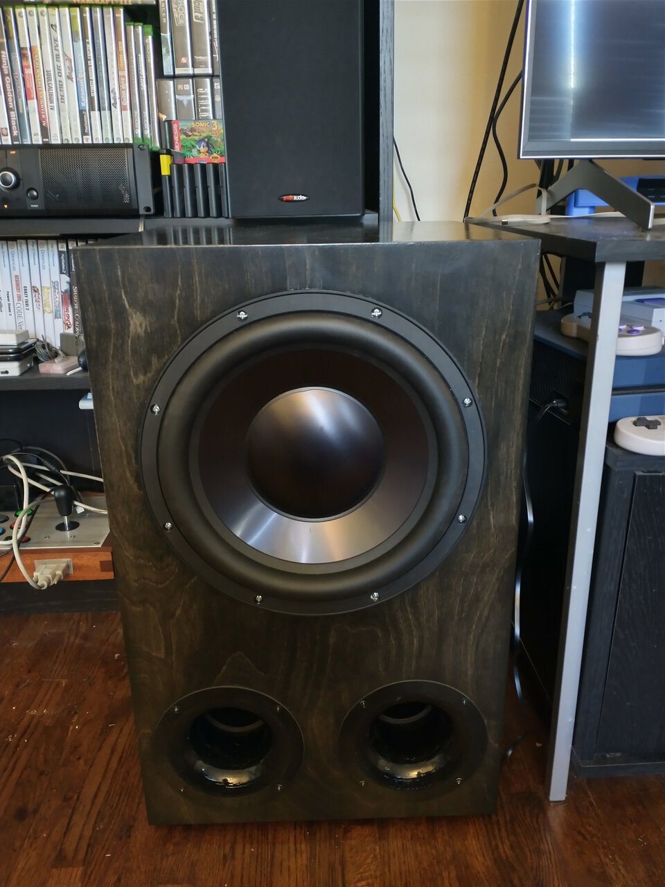
I cannot express how happy I am with how this came out. It's deep, it's loud, it looks good. At normal volumes it's noticeable how much of a difference it makes and if you crank it up it shakes the house.